Hi
To draw lines on a map, I have already used DrawPrimitive2D. Now, in a 3D world, I want to show the connection between different objects and represent it with a line. Let’s say, for example, which person belongs to which house. And then display this connection with a line.
Thank you very much for your help.
There are 2 sensible ways:
-
You can define a set of lines using TLineSetNode and place them in TCastleScene. In effect, you have TCastleScene instance that you can add/remove to a viewport at any time (and you can of course change the lines, even every frame).
Example:
examples/physics/physics_forces/. See how it manages “debug lines” incode/gameviewmain.pasunit: https://github.com/castle-engine/castle-engine/blob/master/examples/physics/physics_forces/code/gameviewmain.pas . It defines two line shapes (2x instances ofTLineSetNode), one to visualize physics angular forces, one to visualize physics linear forces. They are both places in one SceneVisualizeVelocities . Look there atTViewMain.CreateVisualizeVelocitiesNodesandTViewMain.UpdateVisualizeVelocitiesfor code creating / updating them. You can likely make it simpler for your specific use case
-
Use TCastleRenderUnlitMesh . This offers a bit different way of thinking: instead of having to add / remove your lines, you instead use the
TCastleRenderUnlitMeshproperties and theTCastleRenderUnlitMesh.Rendermethod to draw the lines each time from some TCastleTransform.LocalRender override.Example: See
examples\research_special_rendering_methods\test_rendering_opengl_capabilities\, it defines a simpleTMyMeshclass (descendant of TCastleTransform) that internally usesTCastleRenderUnlitMeshto render each frame a bunch of lines.
Which one to choose? I would generally advise AD 1. It allows to think “declaratively”: you define a set of lines, add them to viewport, and you’re “done” – the lines will be there, visible, you don’t need to worry about rendering them.
AD 2 allows to think more “imperatively” – every frame you have to define the lines and call TCastleRenderUnlitMesh.Render to see something.
Ultimately they both makes sense, and we are committed to supporting them both, and they are both very efficient.
1 Like
With the code below, I can see lines, it works great.
Now, let’s say I draw 100 such lines and they all start at different places, so they are not connected to each other.
I tried creating multiple “shapes” to achieve this, but it seems to become very slow when there are many different scenes (with AddChildren(shape)).
Is there a way I could use the same “lineSet” and add new line coordinates to it, but with a “reset” in between so that the lines are not connected to the previous ones, but positioned anew?
And in the end, I would only have a single AddChildren(shape) which would be drawn much faster.
I had used a “reset” in another example with: indexFaceSet[1].FdCoordIndex.Items.Add(-1); But with the structure below, I’m not sure how to incorporate it.
Once again, thank you very much for your help.
procedure UpdateRectangleCoordinates;
begin
RectCoords.SetPoint([
Vector3(0 , 0, 0),
Vector3(10, 10, 0),
Vector3(120, 120 , 120),
Vector3(5, 5 , 5),
Vector3(15,15,15)
]);
end;
var
Shape: TShapeNode;
LineSet: TLineSetNode;
LineProperties: TLinePropertiesNode;
Material: TMaterialNode;
Appearance: TAppearanceNode;
begin
RectCoords := TCoordinateNode.Create;
UpdateRectangleCoordinates;
LineSet := TLineSetNode.CreateWithShape(Shape);
LineSet.Coord := RectCoords;
LineSet.SetVertexCount([RectCoords.FdPoint.Count]);
Material := TMaterialNode.Create;
Material.EmissiveColor := RedRGB;
LineProperties := TLinePropertiesNode.Create;
LineProperties.LineWidthScaleFactor := 2;
Appearance := TAppearanceNode.Create;
Appearance.Material := Material;
Appearance.LineProperties := LineProperties;
Shape.Appearance := Appearance;
sceneStack[1].rootNote[1].AddChildren(shape);
Yes, you can put multiple (disconnected) lines in the TLineSetNode. This will indeed be much faster (and usually more comfortable to set up) than creating multiple shapes.
The key is a property TLineSetNode.Mode, see
The default mode is “lmStrip”, which means you have a connected set of lines. But you can use “SetVertexCount” (array of integers) to separate them into groups. E.g. if you do
LineSet.SetVertexCount([3, 3, 4]);
it means that in coordinates (LineSet.Coord) we expect to see 10 vertexes, and
- First 3 vertexes will be connected (thus making 2 lines)
- Next 3 vertexes will be connected (thus making 2 lines), disconnected from previous 2 lines
- Next 4 vertexes will be connected (thus making 3 lines), disconnected from previous lines
Mode “lmLoop” is similar, but each “group” gets one additional line that makes it a loop.
Finally “lmPair” is most useful when you want just a set of potentially disconnected lines. It’s equivalent to OpenGL GL_LINES primitive. Then LineSet.SetVertexCount... is just ignored, and we just create a line segment from each pair of vertexes in coords. That is,
- 1st vertex is connected with 2nd
- 3rd vertex is connected with 4rth
- 5th vertex is connected with 6th
…
Note that the example physics_forces I linked previously uses LineSet.Mode := lmPair;, see castle-engine/examples/physics/physics_forces/code/gameviewmain.pas at master · castle-engine/castle-engine · GitHub .
Hi guys, I too am wanting to draw some lines in 3d… to show the route that is set on a car. The cars currently try to drive to the ‘store’ using the nearest road. It builds a 2d route for vehicle, which it tries to follow, but can deflect from based on physics and the terrain. In the picture below I would hope to see a red line 1 unit above the ground on the road where the track intersects the road, to the road where it intersects again by the store, and then to the store. But I don’t see anything. I am using basically the code from the physics lines (option 1). (ps TRoute is an old style TCollection of TWaypoint which contains the 2d vector locations on the map)
function BuildRouteGraphic( route   : TRoute;
                            terrainheight : THeightAboveTerrainEvent ) : TX3DRootNode;
 var LineSet : TLineSetNode;
     Appearance: TAppearanceNode;
     Material: TUnlitMaterialNode;
     Shape : TShapeNode;
     Lines : TCoordinateNode;
     i : integer;
     wp : TWaypoint;
     pt : TVector3;
 begin
   result := nil;
   assert( assigned( route ));
   if route.count > 0 then
    begin
      Result := TX3dRootNode.Create;

      Material := TUnlitMaterialNode.Create;
      Material.EmissiveColor := RedRGB;

      Appearance := TAppearanceNode.Create;
      Appearance.Material := Material;

      LineSet := TLineSetNode.CreateWithShape(Shape);
      LineSet.mode := lmStrip;
      Shape.Appearance := Appearance;

      Result.AddChildren( Shape );

      Lines := TCoordinateNode.Create;
      LineSet.Coord := Lines;

      Lines.FdPoint.Items.Count := route.count;
      for i := 0 to route.count - 1 do
       begin
         wp := TWaypoint( route.at( i ));
         pt := vector3( wp.TargetPoint.x, 0, wp.TargetPoint.y );
         terrainheight( pt, pt.y );
         pt.y := pt.y + 1;
         lines.FdPoint.Items.L[i] := pt;
       end;
      Lines.FdPoint.Changed;
    end;
 end;
then where the route is built, it calls with this code to add to the scene…
x3dRoute := BuildRouteGraphic( TAction_DriveOffroadToNearestRoad( Vehicle.Movement ).route,
                                         @HeightAboveTerrain );
          if assigned( x3dRoute ) then
           begin
             RouteGraphic := TCastleScene.Create( self );
             RouteGraphic.Load( x3dRoute, true );
             MainViewport.Items.Add( RouteGraphic );
           end;
Am I missing something?

update: maybe I am using lmStrip wrong? If I change it to lmDual, I do see the first segment of the polyline.
update2: I needed to add
LineSet.SetVertexCount(route.count); for lmStrip. Now it works as expected. Thanks anyways.
1 Like
Drawing lines works wonderfully and is also very fast even with hundreds of lines.
Now I’m considering how I could draw billboards.
For other objects, I used
-coords.FdPoint.Items.Add
-textureCoords.FdPoint.Items.Add
from the example “CastleCraft,” which is also very fast.
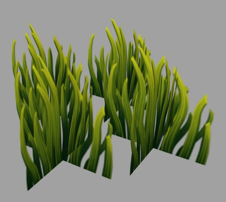
So, I want to fill hundreds of clusters of grass (as a billboard-image) around the camera and then pass them to the scene. These clusters are distributed at different positions, each with the same texture (only the size should vary to avoid looking like the same grass).
Would these objects automatically rotate towards the camera as it moves, even though they are located at different positions around the camera? Or would I need to redraw them at each step when the camera moves?
But initially, the focus is on creating many billboards at once. If necessary, I can do it like cubes with 3D objects, but I assume billboards would be much faster.
Thanks again for the help.
Indeed, depending on line mode (lmStrip, lmLoop, lmPair) one may need to set vertex count to actually render the lines. The various possibilities are documented at Castle Game Engine: X3DNodes .
I understand this is solved ![]() Sorry for delay in answering!
Sorry for delay in answering!
( Note: This question is a bit outside of the topic of this thread. For further talk about billboards, please create a new thread ![]() )
)
You can make billboards using TBillboardNode (wrap any number of X3D shapes that should be oriented) or TCastleBillboard (attach it to TCastleTransform that should be oriented).
Admittedly I’m not sure if the billboards here will be very efficient enough.
Having lots of 3D shapes, each with 2 quads arranged to form a cross, will be both easier to do and faster to render. Like here: