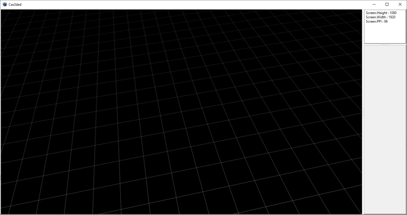
This works but isn’t very efficient as all I really want to create here is a placement grid as used by Blender, Unity, Kenny’s Asset Studio etc which I’ll show in a viewport which I then overlay with another transparent viewport in which I build a proper scene from component model assets. The resulting scene, without the grid, can then be exported as a X3D model, json, a streamed object or whatever else I desire.
So, what’s the best way to create my placement grid? I’ll sync the viewports cameras as needed so any change in viewpoint should result in the grid keeping in sync with the scene being built.
I’m not exactly sure what the “placement grid” is. DuckDuckGo shows me images different from the one in the screenshot above. Maybe you’ve meant “coordinates grid”?
If yes, then you don’t need transparent Viewports (which would raise a lot of problems of its own, e.g. Z-sorting). You need to keep it in a separate TCastleScene in the same Viewport - and simply don’t save this specific scene with the rest of the project.
And you don’t need loading multiple objects. The coordinates grid can be just a textured plane (quad) with semi-transparent texture. Some earlier versions of Blender even cheated and made it a finite plane with a predefined size (like seen here https://i.stack.imgur.com/WzRqS.gif), though it is not too hard to create this plane by code to cover the whole visible area.
Even if you want to use it as a “placement grid” (like Tiled or any other grid-based editor), you can just convert mouse clicks in the Viewport into discrete set of coordinates and add objects there. Obviously it’s more complicated in 3D than 2D, but still should be relatively easy to.
Err - didn’t know what the technical name for it was - it’s a grid you use to place things on so I went with placement grid
The textured plane approach is a good I guess. I’ve been thinking too literally. If I use a repeating texture that’s 1x1 (co-ordinate space) in size tiled forever then I should end up with the desired result - I think…
Hmm, could use a MipMap? That could provide that nice effect Blender has that when you zoom out by 10x the smaller grid gets replaced by variant indicating the zoom.
Overlaid viewports are a nice tool. I’ve played with them a little with to very good results.
The ground plane is a 1x1 with a repeating texture - I tried three versionsplane.zip (3.2 KB)
The OBJs in the ZIP are all the same apart from the texture used…
plane.obj uses white on black
plane_transparent.obj uses white on black with opacity 0 (i.e. fully transparent)
plane_transparent_16.obj uses white on black with opacity 16 (1/16th transparent)
The image is UV mapped 100 times repeat X+Y but opening them in view3dscene gives results I find confusing.
I ended up using the 1/16 transparent version for now
I adapted the OBJs by hand - it’s easier to learn how to write OBJs than work out how to do the same thing in Blender
Rendering a grid as a plane covered by a (repeated) texture is one approach indeed. It means you need to deal with the way texture is sampled. If you will view this grid under different angles, then be sure to use mipmaps (they are used by default, so just make sure you don’t disable them e.g. by non-default Scene.Attributes.MinificationFilter or ImageTexture.GuiTexture = true).
The texture will get blurry far away (when viewed from a steep angle), that’s just how texture sampling using mipmaps work. To fight with this, use also anisotropic filtering. To do this, add “TextureProperties” node with “anisotropicDegree” set to something high (like 16). See https://castle-engine.io/x3d_implementation_texturing.php about TextureProperties. You can look at the log https://castle-engine.io/manual_log.php to see the maximum anisotropic values (they are specific to each GPU, higher values than maximum are just equal to maximum).
The demo of anisotropic filtering is in demo-models, get https://github.com/castle-engine/demo-models and open “texturing_advanced/tex_anisotropic.x3dv” e.g. in view3dscene (or any other engine tool to view scenes).
Another approach to render a grid, that I would actually advise (because it means you no longer need to deal with texture filtering, transparency) is just to use a LineSet X3D node to define all the lines as a single X3D shape.
Note that you can update the lines coordinates by code. So if you need to move the grid (because the camera moved) you can do it, just call TCoordinate.SetPoint(...) on the Coordinate node you used with lines shape.

